Friday, October 30, 2015

DIY Track Pickup Wipers

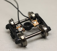
With the release of our Tsunami SoundCar decoders for rolling stock and our recent production of Blackstone Models 30-Foot Refrigerator Cars with a "SoundCar-ready" design, this post provides step-by-step instructions for making your own pickup wipers. While we considered including pickup wipers on the refrigerator cars, we opted to leave them out due to the significant price increase they would add to the models. Fortunately, it's relatively easy (and inexpensive) to make your own. One method that we like is to modify Kadee® No. 5 Centering Springs (Item #634) as pickup wipers, which are available for $2.97 per dozen. The springs' “arms” can easily be modified to work as wipers on the inside of the wheels by mounting the centering spring on top of the truck bolster and soldering the pickup wires directly onto the centering springs.

Note: We suggest installing track pickup wipers on more than one truck for best results.

For a demonstration of one of the methods for adapting the springs as pickups, watch our video:


There are two methods for this installation: solder/glue method and drill/screw method. 


Solder/Glue Method
Solder wires directly onto the centering springs, then glue the centering springs to each side of the plastic truck bolster.

Materials
  • Kadee No.5 centering springs (2)
  • 28 to 32-gauge wire
  • Wire strippers
  • Wire cutters 
  • Drill
  • 25W soldering iron 
  • Rosin core solder 
  • Tweezers
  • File
  • Modeling glue
  • Toothpick
  • Heat-shrink tubing
  • Heat gun or blow dryer
Installation
  1. Remove trucks from model and set screws aside.
  2. Remove wheelsets from trucks; gently spread apart the frame and pull out the axles. Set wheels aside.
  3. Bend the spring leaves out and away from the each plate with tweezers.
  4. Using wire cutters, halve each plate so that the side with the attached spring leaves can be used. The side with the hole can be discarded.
  5. Cut two 4-5” lengths of wire.
  6. Strip and tin one end of each wire.
  7. Solder a wire to the center of the topside of each plate.
  8. Run a file across the top of the plastic bolsters and along the bottom of the metal plate to roughen each surface. This will allow the glue to hold the centering springs to the bolster more securely.
  9. Approximate the placement of the centering springs to ensure the spring leaves will lightly, but evenly, touch the inside area of each wheel. Do this by matching it up with another set of trucks.
  10. Use a toothpick to apply glue onto the coarse topsides of the bolster and the bottoms of the plates. Glue the centering springs into place.
  11. Reinstall the wheelsets after the glue has dried. Ensure the spring leaves are wiping the inside of each wheel and make adjustments as needed. Ensure the spring leaves are not riding the insulating bushing on the axle.
  12. If necessary, drill two holes in the underframe of the model (one hole for each wire) and thread the wires through the underframe.
  13. Bend the wires to ensure they will not interfere with the bolster. Screw the trucks back onto the underframe.
  14. Strip and tin the red SoundCar wire (right rail), black SoundCar wire (left rail), and the remaining ends of the wires.
  15. Slide a piece of heat-shrink tubing over each wire.
  16. Solder the red SoundCar wire to the pickup wire for the right rail.
  17. Solder the black SoundCar wire to the pickup wire for the left rail.
  18. Slide heat-shrink tubing over the connections and heat with a heat gun or blow dryer to insulate.

Drill/Screw Method
Drill a hole through each side of the bolster and each centering spring, then entwine the stripped end of the wire around a 1-72 sized screw and fasten it through the centering springs and bolsters.
Materials
  • Kadee No.5 centering springs (2)
  • 28 to 32-gauge wire
  • Wire strippers
  • Wire cutters
  • Tweezers
  • Drill, drill bit, and tap
  • 0.25”, 1-72 roundhead screws (2)
  • Modeling glue
  • Toothpick
  • Heat-shrink tubing
  • Heat gun or blow dryer
  • 25W soldering iron
  • Rosin core solder
 Installation
  1. Remove trucks from model and set screws aside.
  2. Remove wheelsets from trucks; gently spread apart the frame and pull out the axles. Set wheels aside.
  3. Modify the Kadee centering springs (2) so they fit neatly atop each truck bolster and do not cover the screw holes for mounting the trucks.
  4. Bend the spring leaves out and away from the plate with tweezers.
  5. Using wire cutters, halve the plate so that the side with the spring leaves attached can be used and the side with the hole can be discarded.
  6. Drill a hole through the middle of each side of the bolster and a hole through the center of each plate. These holes must be sized to support 1-72 screws. Tap hole for a clean mount.
  7. Cut two 4-5” lengths of wire.
  8. Strip one end of each wire about 1”.
  9. Approximate the placement of the centering springs to ensure the spring leaves will lightly, but evenly, touch the inside area of each wheel. Do this by matching it up with another set of trucks.
  10. Entwine the stripped end of each wire with each 1-72 sized screw, and fasten them through the holes drilled in the centering springs and bolsters. A wire should now be secured through both centering springs and into each side of the bolster. This will allow a metal-on-metal connection to deliver electricity to the SoundCar.
  11. Reinstall the wheelsets. Ensure the spring leaves are wiping the inside of each wheel and make adjustments as needed. Ensure the spring leaves are not riding the insulating bushing on the axle. 
  12. If necessary, drill two holes in the underframe of the model (one hole for each wire) and thread the wires through the underframe.
  13. Bend the wires to ensure they will not interfere with the bolster. Screw the trucks back onto the model.
  14. Strip and tin the red SoundCar wire (right rail), black SoundCar wire (left rail), and the remaining ends of the wires.
  15. Slide a piece of heat-shrink tubing over each wire.
  16. Solder the red SoundCar wire to the pickup wire for the right rail.
  17. Solder the black SoundCar wire to the pickup wire for the left rail.
  18. Slide heat-shrink tubing over the connections and heat with a heat gun or blow dryer to insulate.

Thursday, October 1, 2015

Tech Tip: Setting Up an Emergency Brake Light with Econami

With our new Flex-Map function mapping technology in our value line of Econami Digital Sound Decoders,  you can easily set up an emergency brake light effect to come on when the E-Stop button is pressed.  

For example, to set the FX3 lighting output as an emergency Gyralite that is activated when the E-Stop button is pressed, follow these steps: 
  1. Access CV 51 (FX3 Configuration) and set it to a value of 21 to configure the emergency Gyralite Hyperlight effect to the FX3 lighting output. Note: The Hyperlight effect configured to the FX3 lighting output can be turned on with function key F24 by default.
  2. To map the emergency Gyralite configured to the FX3 lighting output to the emergency stop button, access CV 1.387 (FX3 Effect Auxiliary Map Register).
  3. Set CV 1.387 to a value of 16. 

For additional information, refer to the “Configuring Lighting Outputs” and “Function Mapping” sections of the Econami User’s Guide

Thursday, June 4, 2015

Building Pride, One Digital Sound Decoder at a Time

Architect rendering
When you ask what she’s looking forward to the most about the new SoundTraxx facility, the immediate answer from  co-owner and Vice President Nancy Workman is, “Having everyone in the same building!”

Getting the company under the same roof is the essential idea, and she elaborates by saying, “We’re able to be more competitive in manufacturing when we have a technologically advanced production floor. Over the years, we’ve updated our equipment with faster machines and better technology to maintain control of labor costs, gradually becoming larger in the limited space we have for production. We have run out of room in our current facility -- to the point that our engineering staff has been relocated to a rented space down the street.”

With the new building, our production and administrative areas will expand from 6,000 square feet to 20,000 square feet of much-needed space.

Production floor
The ground level is designed to further accommodate the implementation of “Lean” manufacturing methods to improve efficiency and eliminate waste. Production Manager Brad Schulz is looking forward to having this specifically designed area to improve manufacturing flow. He explains that, “having the opportunity to design a manufacturing space from scratch can be very conducive to our efforts to operate under Lean methodologies. We will begin with raw materials on one end of the manufacturing line and end with finished product on the other, which will eliminate or reduce the activities that don’t add value along the way.”

Maintaining efficiency in the manufacturing process is key to our commitment to produce Digital Sound Decoders in the USA. According to Brad, this allows us to control aspects of manufacturing such as quality, cost, and frequency of production. He further describes that, “by keeping our manufacturing operations here in the states, we have the ability to be extremely agile when it comes to fulfilling orders or responding to market conditions.” Because efficiency will no longer be compromised by space constraints, the new facility has also been designed for what Brad refers to as, “calculated and efficient expansion” for keeping production costs down, and, in turn, for a lower product price.

East side of the building
We stand behind our products and USA-based manufacturing to strengthen quality control and provide you with top-drawer products. We design our test fixtures and check the operation of decoder before it’s shipped. If problems arise, our engineering team is right there to troubleshoot and prevent issues from hindering the manufacturing process. Our efforts are focused upon creating the highest quality products for users, and this dedication is what has built the company from the ground up.

Regarding the building design, Nancy adds that, “While we're not pursuing actual certification, we are following LEED practices when possible to reduce the building’s environmental impact.” Standing for “Leadership in Energy and Environmental Design,” LEED is a set of rating systems that specify the design, construction, operation, and maintenance of what is commonly referred to as “green.” She calls it “LEEDing by example,” which is expressive to the role SoundTraxx plays globally and locally, especially in an environmentally-aware city like Durango, Colorado.

Nancy in her soon-to-be new office
The new building will also foster an enhanced environment that supports employee well-being. For example, it will include an employee fitness center, as well as a patio complete with a grill for informal gatherings. There will also be more spaces for meetings and product development, including a library area where employees and guests can collaborate or relax. Also among the building's centerpieces will be a model train layout designed and built by SoundTraxx employees. Though, most importantly, the new building will bring all employees back under one roof.

Progress at week 35
If you have plans to come to Durango this fall, you may find us preparing for the move, in the process of moving, or we could already be moved in! You don’t need a GPS to find us (the new facility is across the road from our current location in the Durango Tech Center) and we’re looking forward to showing you around! A virtual tour will be available online when we’ve moved in, and we’ll be happy to give tours if you find yourself in the area. Please contact us at (970) 259-0690 or (888) 789-7637 to schedule a tour. Tours are offered Monday-Friday at 4:30 pm, and we do our best to accommodate specific times.

Tuesday, May 19, 2015

Realistic Operations with Tsunami's F11 Braking Feature

Give your throttle a “brake” and use F11 to slow your train. Instead of adjusting the throttle to engage the brakes, our functioning brake effect lets you apply the brakes (and play the brake squeal sound effect) with the press of the F11 function key. We developed the F11 functioning brake feature to add another level of interaction and realism to prototypical operating sessions. This feature is available in our Tsunami Digital Sound Decoders and DCC Mobile Decoders.

F11 Braking on the Mainline

To use this feature, first adjust the locomotive’s momentum by setting CV 3 (Baseline Acceleration Rate) and CV 4 (Baseline Deceleration Rate) to non-zero values. The exact values are up to you, but they should be large enough to produce a noticeable delay in throttle response. We recommend starting with CV 3 set to 25 and CV set to 75. Then adjust the values to your personal taste from there. Next, program CV 61 (F11 Braking Rate) to adjust the rate at which the locomotive will slow down when F11 is engaged. If CV 61 is set to 0 or 128, pressing F11 will only play the braking sound effects and not change the locomotive speed. Programming CV 61 with a value from 1 to 127 will simulate a greater load/steeper grade, causing the locomotive to decelerate more gradually than if you simply turned down the throttle. Values from 129 to 255 will cause the locomotive to decelerate more aggressively than if you adjusted the throttle. For this reason, be careful not to set the CV 61 value too high -- it can turn F11 into an emergency stop button. To get started, we recommend setting CV 61 to a value of 178.

To apply the brakes and activate the sound effect, simply press F11 and your train will slow to a stop. Press F11 again to release the brakes and resume running your train.

This feature works really well in conjunction with our Tsunami SoundCar Digital Sound Decoder for rolling stock. Program the values of CVs 3, 4 and 61 in the SoundCar decoders to match the values in the locomotive's decoder when in a consist. This will sync the momentum and braking rates in the consist when F11 is engaged so you can experience full braking throughout your train.

Recommended F11 Braking CV Values
If CVs 61 (F11 Braking Rate) and 4 (Baseline Deceleration Rate) are set to values that do not slow the train quickly, changes in the train speed will seem nonexistent to the operator and spectators. Therefore, we recommend starting with the following CVs and values, and then adjusting them to your preferences.
  • CV 3: 25
  • CV 4: 75
  • CV 61: 178

F11 Braking for Yard Switching

Our F11 functioning brake feature is also great for shuffling cars in the yard.

Simply press F11 to apply the brakes, couple to the unit (press F12 to activate the coupling sound effect), change direction, and press F11 again to release the brakes. With this application, you don't need to worry about adjusting speed steps on your throttle. And since the F11 braking feature is available in the Tsunami SoundCar, this method works great for cutting cars into your consist, especially with our new Intelligent Consisting feature to easily synchronize the cars to the decoder settings in the locomotive.

F11 Braking for Brake Testing

You can also use the F11 feature to simulate brake testing.

A brake test is carried out when departing a yard or depot to ensure the brakes are working correctly. The engineer reduces the brake pressure so the brakes will grip the wheels. The more pressure that's released, the more the brake shoes will grip the wheel. The idea is to verify that the pressure is being reduced properly through the line, which would then, in turn, apply the brakes when required. The test is a fun sequence that can be reproduced when departing any terminal and provides a more realistic operation for your railroad.

First, press F11 to set the brakes. Then press F3 (short whistle/horn) to signal that the brakes are set. Then, wait a few seconds for the conductor to signal to the engineer that brake pressure was reduced throughout the trainline. Press F3 twice to acknowledge the signal, and press F11 to release the brakes. 

For detailed information about programming the F11 functioning brake feature, refer to page 61 in the Tsunami Steam Sound User’s Guide, or page 51 in the Tsunami Diesel Sound User’s Guide.


To see all the F11 braking applications described in this post, watch our video:


Monday, May 11, 2015

Maximizing Speaker Performance with the 7-Band Equalizer

The 7-Band Equalizer works just like the sliders
found on stereo systems to maximize speaker performance.
It's easy to get great sound from any speaker using the 7-Band Equalizer (EQ) feature in Tsunami and Econami digital sound decoders.

The EQ is controlled by eight Configuration Variables (CVs), which allow you to cut or boost frequency ranges to maximize speaker performance. Some CV adjustments are obvious (e.g., cutting frequencies not within the speaker’s range), while others can be tuned to your personal preference. Frequency ranges for SoundTraxx speakers are available on our "Speakers" page.

The Equalizer Control Register CV (CV 153 in Tsunami, CV 225 in Econami) allows you to select preset cut/boost levels configured for various speaker sizes and types, or enable the user-adjustable setting. There are seven associated CVs (all defaulted to 128) that act as sliders to boost or cut corresponding frequency ranges (CVs 154-160 in Tsunami, CVs 226-232 in Econami). Values from 0 to 127 reduce the output from -12 decibels (dB) to 0dB, and values from 128 to 255 increase the output from 0dB to +12dB.

Adjusting these frequencies will provide the ultimate tone control and help you get the most out of the speaker’s strengths.

Tsunami and 35mm x 16mm Speaker EQ Setting Example

Tsunami 7-Band Equalizer CV Adjustments 
For this example, we'll use Tsunami and our popular 35mm x 16mm speaker. First, enable the user-adjustable EQ by setting CV 153 to 7. CV 154 controls the 62Hz frequency band, which is too low for this speaker to physically reproduce (its lowest frequency is 250Hz). Set this CV to 0 so the speaker will not cause any distortion. Likewise, CV 155 controls a frequency that is too low for this speaker (125Hz), so also set it to a value of 0. CV 156 controls the 250Hz frequency band, which is the starting threshold of the speaker’s capabilities. You can boost this a small amount, so set CV 156 to 175. The rest of the CVs (157-160) are in the speaker’s frequency range as well. We suggest starting with the following values and then altering them to your preference: CV 157 = 200; CV 158 = 225; CV 159 = 200; and CV 160 = 185). Try different settings and listen for what sounds best to you. Record your changes so you don’t forget the settings you liked.

Recommended EQ CV Values for SoundTraxx Tsunami Decoder and 35mm x 16mm Speaker
  • CV 153: 7
  • CV 154: 0
  • CV 155: 0
  • CV 156: 175
  • CV 157: 200
  • CV 158: 225
  • CV 159: 200
  • CV 160: 185
  • Note: You may adjust CVs 156-160 to your personal preference.

For more information regarding the EQ, refer to the user's guides on our "Manuals" page. Our “Sound Primer” also details the science behind sound and has tips for speaker installation. You can also watch our EQ demonstration video:


Thursday, January 29, 2015

How It All Began. . .

In this post, Nancy Workman, Co-owner and Vice President for Sales & Marketing, recalls how SoundTraxx got its start...

As we begin our 25th year in business, a rare bit of nostalgia creeps in….25 years! How did that happen?!

Way back in 1988, I began working for a marine electronics company in Pocasset, Massachusetts. The company primarily designed, manufactured and sold electronics for recreational marine use -- charting machines, knot meters, depth sounders, and wind anemometers. My new job entailed mostly marketing, but I was also responsible for writing the owner’s manuals that went with our products. As fate would have it, my first manual was for a series of products being developed by one of the senior design engineers -- one Steven Dominguez. 

During the process of writing the manual, Steve and I became friends, and early in 1989, he approached me with a request: Would I have some time to help him market a product of his own that he had been working on? My first question, of course, was, “What’s the product?”

Very seriously, he answered, “It’s a sound system for model trains.” To which I skeptically answered, “…A sound system for toy trains?” Steve snorted at me and answered, “NO! SCALE MODEL TRAINS!” To which I responded, “What’s the difference?”

Please understand, I have never been exposed to model railroading. No uncles, brothers or grandparents, no neighbors, nothing in school. I really didn’t know the difference. At this point he huffed out of my office and I pretty much figured that was that. But the next day, he walked in and put a model -- an HOn3 brass Fujiama K-36 -- on my desk. As a former art major, I could totally appreciate what it represented. I said, “That’s the coolest thing I’ve ever seen” and the rest, as they say, is history.

Later that year, Steve and I attended (as registrants) the National Narrow Gauge Convention in Durango, Colorado. It was there that I fell in love with the area, the Durango & Silverton Narrow Gauge Railroad, and the modeling community. We launched our company in January of 1990, with an eye on someday moving to Durango and creating cool products for our new friends. Though the first product launched was actually not a sound system, but our Hyperlight, it began a quarter-century of innovations that we continue today. 

We hope you stay tuned -- we have lots of exciting things coming in 2015! And celebrate with us by visiting our 25th Anniversary Web page on the 25th of each month for our "Silver Special" offer or announcement. For our first "Silver Special," we're offering steam and airhorn audio files as free downloads for ringtones (or fun sound effects for your computer). 

Thursday, January 8, 2015

Celebrate 25 Years of Innovation with Us!


January 2015 marks the launch of our year-long celebration of 25 years in designing and manufacturing innovative electronics and sound systems for model railroads. 

Throughout the year, we’ll be offering “Silver Specials” to thank you for your support. Check our 25th Anniversary Web page on the 25th of each month for a special offer, contest, raffle, or giveaway.

It all started when...


Owners Steve Dominguez and Nancy Workman launched SoundTraxx’s corporate entity, Throttle Up!, in 1990. On February 4, 1990, they debuted their first product, the Hyperlight HPL-75, at the Big RR Hobby Show (now known as the Railroad Hobby Show) in Springfield, Massachusetts. The Hyperlight was the first lighting product on the market that used a microprocessor to allow users to select and control multiple lighting effects from within one module. Modelers were able to select from more than eight effects, which included Mars/Gyralite, oscillating headlight, rotary beacon, xenon strobes, and a fire flicker effect. They also could set directional lighting and flash rates. The heritage of this product is still evident today in our line of Tsunami Digital Sound Decoders.
Our first product, the Hyperlight

The Hyperlight is one of many industry “firsts” that we have developed over the past 25 years. In 1996, we released our first Digital Sound Decoder – the DSD-2408 for steam. This revolutionary product was the first DCC decoder that included both sound and lighting functions, as well as the first to feature polyphonic sound channels and Dynamic Digital Exhaust

Today, we’ve continued to push the envelope for what’s possible with DCC to add more realism and fun to model railroading. Our Tsunami line of Digital Sound Decoders still feature many of the technologies we’ve developed and built upon since the beginning. What innovations will we bring to 2015? Stay tuned…